A blog devoted to professional aspects of design
and engineering applied to the art of fine woodworking.


December 31, 2012

Same But Different

Along with several posts written about the concepts and philosophy behind my design process and workshop layout, this blog has covered the construction of two rather simple projects this year. The first of these was an iPad stand, and the second is a set of candle holders I just completed this past weekend. The two projects pictured here appear different, but yet are almost the same.

Both designs have four tenoned legs that are glued into the slot mortises of a central block. That block in turn supports a platform that supports an item that needs holding. In one design that item is a candle. In the other that item is an iPad. Both designs appear almost identical from the perspective of the workshop, and so were therefore conceptually supported during their respective build processes quite successfully by the adaptive workcell arrangement around which I built my Minnesota shop.

There is much more to learn about manufacturing under the principles of Group Technology and the relationship that the broader concept of Design for Manufacturing has on producing a product family. I talked about common design architecture in an earlier post where I described a set of different lamp stands I built that were based on a common product platform architecture. The candle holders and iPad stand are just as much a product family based though on a common build architecture.

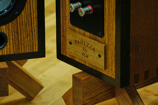
Update: I just completed building a set of objects to act as prototype fixtures for tungsten filament light bulbs. These are described in a later entry. You can see in the one whose photo I've added here that the concept of a central block with four tenoned legs is used yet again.

My walk in to work each morning usually takes me through the Mechanical Engineering building at the University of Minnesota. Two useful books on this topic that I found on the free book table there a couple of summers ago are listed below.

Meyer, M., & Lehnerd, A. (1997). The Power of Product Platforms. New York: The Free Press.
Sanderson, S., & Uzumeri, M. (1997). Managing Product Families. Chicago: Irwin.

I also found the following white paper a good source of recent information on this topic.

Parametric Technologies Corporation. (2012). Achieving Product Diversity with Scale.

The metal candle dishes for the candle holder project were provided by Marlaine Cox Metalworks.

December 2, 2012

And Then There Were Eight

Recall from my previous post that I am making a set of blocks for a Christmas project that each have four slot mortises routed on one face, and a circular extruded cut feature routed on the other.

The slot mortises were easy to rout using the CNC router, and since they will accept a matching tenon, they only needed to be accurate.

The circle features on the other hand need to be free of visual defect which I found more difficult to accomplish given the nature of the two woods I am using.

Padauk and zebrawood easily splinter, and the router bit also tends to burn both woods more easily than others. I found that slowing the speed of the router to somewhere around 12,000 rpm and increasing the feed rate of the cut removed any tendency of the router bit to burn the wood. It was actually surprising that this combination of speed and feed rate also produced an almost splinter free cut.

What a relief.

There were originally nine blocks. The problem of speed and feed rate did not appear on the initial test run using a scrap of medium density fiberboard. It only became apparent on the first block of zebrawood.

This unfortunately happens sometimes.

That first block of zebrawood is now a block of sacrificial scrap. It was used to perfect the cnc routing process for the circles, and will be useful to test a future process that might need verification before committing that process to the other eight blocks.

December 1, 2012

Accurate Repeatability

I began a small project this week that I hope to have completed by Christmas. The design is based on a square block of wood with four slot mortises routed at each corner. A larger circular feature is routed on the opposite face of the block. There are nine blocks in all.

In total then there are thirty-six slot mortises to route. Repetitive accuracy is a requirement so the use of the CNC router was a natural choice for machining the mortises.

The design solid model served as a starting point for geometry on which to base the slot mortise tool paths. The following segment of machine code represents a single pass at depth. There are multiple passes for each slot, and each pass plunges into the block by a fixed distance until the final depth is achieved.

F14.0
G00 X0.5938 Y0.5313 Z0.2000
F11.0
G1 X0.5938 Y0.5313 Z-0.0620
F14.0
G01 X1.7813 Y0.5313 Z-0.0620
F14.0
G00 X1.7813 Y0.5313 Z0.2000


The two left mortises both top and bottom are routed together, and since the block is square and its features symmetric, it was simply rotated to produce the remaining mortises on the opposite side of the block. Doing it this way allowed the block to be clamped to the table on one side while routing took place on the other.

The routed mortises will accept tenons from four legs that support the block as a platform of sorts. It should begin to be apparent what this project is all about.

November 17, 2012

Common Architecture Based Design Derivatives

The need for something to hold some lamps on prompted me to build a set of four lamp stands rather than go out and purchase something adequate, but maybe not exactly what I was looking for. My place is rather space-constrained, so I thought it would be a good idea to combine functions and use the stands for additional storage.

Two things that came to mind at the time I was building them were storage for compact discs and wine bottles. I purchase music on compact disc rather than download music from something like iTunes because the sound quality of the average download for me is too far below average.

I did not want to put a lot of effort into building them, so my stands were basically simple frame units that shared the same concept and construction method. Each is formed of two side frames joined by horizontal rails with a top attached. This defines the basic design architecture. By changing the horizontal rails though, each completed unit adopts a unique function. The cd stands have rails with an opposing angled edge while the wine rack stand rails have a semi-circular cutout large enough to cradle the average bottle of wine. Additional color variation was achieved by making the rails from various left over scrap stock that included padauk, tzalam, Peruvian walnut, and old growth white oak.

A lot of the design work was simplified by using parametric solids modeling. Such basic assemblies as the side frames could be reused in each design derivative with little or no modification which also saved construction time in the shop.

This basic design concept can be viewed as a simple product platform producing a small range of product family.

October 13, 2012

Production: An Engineering Perspective

The science of modern manufacturing engineering plays a central role in my work as that work has always had a business component. This may seem antithetical to someone who works solely in the context of true art. For me it has always been a necessity.

My workshop here in Minnesota is as much a space for learning as it is for building, and by learning I mean applying concepts in art and engineering to produce design outcomes and the understanding that those outcomes provide.

I am most interested in exploring the engineering concepts of design through the production of product platform architecture and the production of structural form, and the fundamental visual concepts of subject, form, and unity.These were always principle in organ building, so it is natural that I want to continue their development and study here in my current workshop space building functional design for local galleries.

My design method begins with a produce-first approach that helps to answer the two questions that I most often face. Can I build this thing I am trying to build, and can I build more than one or multiple variations of that one thing? This is why I design from methods or technique, and start with the mortise and tenon or dovetail joint for instance. The integration of a set of basic techniques form the foundation for a product or object platform architecture that, if developed correctly, can easily scale to produce a family of related yet different objects. This is not economy through scale, but a simplification through scalable commonality.

The contribution of manufacturing engineering science to the design of an object begins with an emphasis on production. Build methods and technologies drive the creative process back towards the beginning and result in the creation of an initial product platform architecture.

That there can be a plausible integration between what could be considered true art as human expression, and the introduction of a business case argument in determining a design configuration through the application of production engineering sciences is my current focus in developing new uses for my engineering aptitude.


September 22, 2012

Constructing Art: A Renewed Focus

Taunton Press recently released a limited edition reprint of the first edition of Fine Woodworking magazine first published in 1975. The magazine was originally devoted to advanced woodworkers and woodworking as fine art. I thought it might be interesting to purchase this edition because my own craft and organ building workshop practice had grown out of an era that began during this time when the use of wood as a sculptural material was far more used in practice than it probably is now.

The first edition reprint reminded me of that time when large cast iron ruled. A workshop was considered no more than a table saw, band saw, jointer, and planer with possibly a router, drill, and sander thrown in. Hand tools such as a good set of chisels along with a plane or two completed the inventory.

Someone more research oriented than I am should write a better history, but after some time, the home improvement scene hit, and tool makers began concentrating their design and product efforts on this. A much wider array of innovative cordless, benchtop, and job-site tools can now populate a workshop space, and I have chosen to replace a lot of cast iron in the current manifestation of my workshop layout with this type of tool design.

I admit that until now, I have spent more effort here in Minnesota on technique, technology, and methods, and as a result, far less on actual design and construction much to the absence of a portfolio. I recently began to feel in fact a broken continuity to the work I did before as a pipe organ builder, and so have taken a back-to-basics approach, and have begun to study basic fundamentals and concepts of visual art.

Art does not have to be ironic, or a statement of disenfranchisement, or even playful or whimsical as is often thought. A functional object can make its own statement without being any of that, and still incorporate fundamental concepts of visual design to enhance its intended function. That will be my initial direction I think, to understand and appreciate the fundamentals of visual design and how those drive the creation of a work as a unique personal expression or experience, and by doing that, build objects that one can bond with beyond the simple consumer experience that currently defines most forms of ownership today.

September 16, 2012

The Adaptive Workshop

I wrote in my last post about the direction my workshop is heading in towards one that features new innovations in technology and equipment rather than one given over to historic methods. I just finished reading an article in the International Society of Organbuilders quarterly journal about the restoration of a Renaissance pipe organ in France. Of course the original instrument was constructed without the use of any powered equipment, but it appears that hand tool methods were used in much of the rebuild process also.

I have always wanted to someday learn and employ hand tools the way woodworkers did in the past, but then it looks like my workshop heads in the other direction. I am reminded of something the German organ builder Gerhard Brunzema once said to me when I asked him why he didn't build instruments more directly in the historic style. He said that since he lived and worked in our time, it would make sense for him to build organs for our time, and not build in the past.

I am reminded once again of this, and therefore am more content at the direction that my workshop and the work that I produce within that shop is taking. Perhaps someone will look at my work a hundred years from now, judge it as something built during its time, and hopefully find validity in that.

More than just modern tools though, I also employ a number of them on tool stands rather than workbenches. Tool stands are usually associated with, and really designed for use on, the job-site rather than in an off-site workshop. My shop is actually space constrained relative to the number of tools I use to accomplish the growing number of methods I now use in my work. I therefore use portable tool stands to set up an occasional job-site within my workshop based on some particular process. The tool stands allow quick set up so that my workshop is able to adapt quickly to some operation, and then adapt back again to another configuration depending on the particular course of a project.

August 26, 2012

The Science of Studio Craftsmanship

I built my last pipe organ, and then moved to Minnesota with the intention of building up a new workshop that would allow me to explore the concepts of studio fine art woodworking in more detail. Most people envision the type of woodworking studio I wanted to build up as the kind that one finds built out of an old farm building far away from a large urban environment, full of old wooden floors, and with hand tools of all sorts hung from the walls. The type of old world workshop with a large workbench or two where one works wood with planes and chisels.

That was my intention. As my workshop builds up, the opposite is happening though. I have begun to employ ever more sophisticated computer design tools, and in parallel built a shop around innovative stationary and benchtop machinery employed in an adaptive workstation environment all to accommodate an increasingly diverse set of processes I now use to build an increasingly diverse set of object design.

I am building object design based on product platform architecture. This is another contemporary concept that might actually not be so far removed from old world craftsmanship if one reviews the extant pipe organ examples of the Baroque organ builder Gottfried Silbermann.

So if someone asks what's he building in there, be sure that it will be some combination of old world and new world craftsmanship. Design making a visual statement, with function and purpose.

July 15, 2012

The iPad: Completed

The iPad became so quickly useful to my work in the shop that I began building a stand for it back in January. The preceding blog posts describe some of the technology and issues that went into building it. And for a while, the project became orphaned while other projects took up my time and resources.

But I completed the project today, and my iPad now has a workbench stand. The iPad has allowed me to go paperless. This is important for many reasons, not the least of which is that I no longer have to carry around a large drawing tube. I use a cloud based file service to store critical project files making those files easily accessible to my desktop computer, laptop, and iPad tablet. This means that each device has the most current version of any design or drawing file accessible at any time.

I print drawing files to pdf format whenever one is created or updated. The iPad app I use to access pdf based drawings and documents on the iPad is neu.Annotate+. Not only can I display a drawing file on the iPad, but neu.Annotate+ allows me to write and save notes on the drawing using a stylus. The project design can later be updated based on the notes I took earlier in the shop. This makes an iterative design-build process that much better managed.

The screen of an iPad is not exactly large. I had been using b-size drawing paper for some time now. No fear though as the viewing area on the iPad can easily be changed, and now it is easy to zoom up on a specific area of interest or small detail. In fact, I no longer include detail views on drawings.

One additional app I find useful to have on the iPad is ShopCalc. ShopCalc is a calculator that works in standard fraction format. This is undeniably great for those of us who seemingly will never go over to the metric system. ShopCalc will however, instantly convert between an English unit fraction and its decimal or metric counterpart.

And one last useful thing. Most tool documentation and instruction manuals are available online in pdf format which the iPad can of course store and access. I have found it very helpful to have a few on hand especially during machine tool setup or maintenance.

February 29, 2012

The iPad: Trade Offs

This entry is about a change I made to the design of my iPad stand and the reason for that change. As the project evolved so too did the set of design requirements. Change is all too often typical in most projects. The only two requirements at first were based on position and footprint. I wanted the stand to position the iPad at a certain height and angle above a workbench close to where I am doing something, and because of that placement on a workbench, it must share space with whatever I am working on. So in that case I wanted the footprint to be relatively small.

I got far enough along in the project to assemble the post assembly to the table. I like what I saw but I began to realize that the design might have a center of gravity issue because the table angles forward placing more weight on the front two legs.

I am not under pressure to get this project done, so I am starting over with a design change that corrects the potential balance issue. The post and two back legs will stay the same, but the front legs are now splayed out from the post at a greater angle. This insures that the design maintains a better center of gravity, and the stand will be less prone to tipping forward.

The stand will now take up more workbench space but is better balanced. There is a trade off in accomplishing that, and it is not unusual for design requirements to conflict with one another. I think this trade off is minimized by increasing the angle on the front legs while keeping that of the back legs the same. This results in a design that still meets position and space requirements while better protecting the iPad it holds.

February 28, 2012

The iPad: Hand Tooled

I didn't notice it until I applied the first coat of finish, but one lower corner of the iPad stand post had a significant chip. The defect could not be sanded or otherwise machined out at this point with the four legs glued on to make up the assembly. So I decided to experiment with some ideas that would transform the defect into a design feature, and decided that the best way to deal with it would be to add a slight bevel to each of the lower post corners.

At this point there would be no realistic method to machine each bevel so I brought out a set of chisels and went to work carving each. I was carving into oak, and upon the first try each bevel came out somewhat irregular. Which was just a perfect match for the organic shape of the CNC routed leg profile. I decided not to perfect them further.

It is interesting how the most basic of hand tool operations using a simple chisel could compliment the technically complex task of CNC routing. Maybe not though since I was the one who either guided the tool against wood or curved a profile on a computer screen to create each.

The iPad: CNC Contouring


My design of an iPad stand has four splayed legs mated to a central post using mortise and tenon joinery. I cut a b-spline profile through one side of each leg to add a sense of organic fluidity to an otherwise angular structure.

The b-spline profile is created in the zx-plane and projected parallel to the y-axis to control the emphasis of linear movement along the height of the stand.

To actually create the contoured profile, I export a computer model into a program called Cut3D by Vectric Software. Cut3D creates the toolpaths and machine code required by a CNC router to shape the surface profile.

Cut3D happens to be a well featured program for creating 3-axis CNC toolpaths. It generates both rough and finish toolpaths, and displays those in animated form for verification.

Also output is an estimation of the time it will take to machine each leg.

The iPad: Building A Stand

I recently purchased an iPad based on what I thought would be its usefulness to my work as a woodworker. It actually exceeded some expectations in that regard. There will be more on how it has in a future post.

Its primary use is in the workshop itself. I find that having a stand to hold it at a proper viewing height while placed on a workbench or table would be helpful. I therefore am going to build a stand for the iPad, and document its construction in the next series of posts.

The design of the iPad stand is almost completed. It has four splayed legs for stability that are attached to a central post. The central post contains a pivot joint that secures a small table for the iPad itself to rest on.

I decided to use my cnc router in interesting ways on this project, and my next post will start this series off with a topic related to that.